Table of Contents
DeviceServer
The device server is an easy-to-use user interface for accessing ZTEX Boards. It's a part of the ZTEX SDK. Main features are:
- Two access methods: HTTP (e.g. using a web browser) and a simple socket protocol
- Supports uploading of Firmware and Bitstream into volatile and non-volatile memory
- Supports simple I/O: read and write to Endpoints
Usage
The Deviceserver can either be started using the bash script DeviceServer in the directory java/DeviceServer or by calling
java -cp [<path to>]DeviceServer.jar DeviceServer <options>
where <path to> stands for the directory where DeviceServer.jar is installed (e.g. the java directory of the SDK package).
If the bash script is used it has to be installed in the same directory as DeviceServer.jar.
Options
The following options are supported
| Option | Description |
|---|---|
| -nc | Do not scan for Cypress EZ-USB devices without ZTEX firmware |
| -id <VID> <PID> | Scan for devices with given Vendor ID and Product ID |
| -sp <port> | Port number for the socket interface (default: 9081; <0: disabled) |
| -hp <port> | Port number for the HTTP interface (default: 9080; <0: disabled) |
| -sa [-]<address>[/<mask>][,…] | Allow or permit HTTP connection from this address(es), see below |
| -ha [-]<address>[/<mask>][,…] | Allow or permit HTTP connection from this address(es), see below |
| -sb <address> | Bind socket server to this address (default: listen on all interfaces) |
| -hb <address> | Bind HTTP server to this address (default: listen on all interfaces) |
| -v | Be verbose |
| -q | Be quit |
| -l | Log file |
| -l2 | Verbose log file |
| -h | Print help |
By default default DeviceServer listens on port 9080 for HTTP connections and on port 9081 for socket connections and only accepts connections from localhost (127.0.0.1). The ports can be changed using -sp and -hp.
Client addresses can be specified using -sa and -sb. Addresses with preceded “-” are permitted all addresses without “-” are allowed. the <mask> value it the number of highest significant bits hat have to math, i.e. a mask value of 24 is denotes the netmask 255.255.255.0. Multiple addresses can be separated by “,”.
Examples
DeviceServer -ha localhost/24,192.168.1.0/24,-192.168.1.10 -sp -1 -v -l2 logfile
Starts the DeviceServer verbosely and only listens for HTTP connections at default port 9080. Connections from 127.0.0.0 to 127.0.0.255, 192.168.1.0 to 192.168.1.9 and 192.168.1.11 to 192.168.1.255 are accepted. A verbose log is written to logfile.
Socket interface
The socket protocol is very simple: the client sends a command delimited by a newline “\n”, optionally payload data and the DeviceServer returns a response.
This simple protocol allows to access the socket interface using command line tools like netcat. For example, the call help returns a list of supported. Options:
$ echo help | nc localhost 9081
Supported commands:
  scan     Scan buses
  info     Print device capabilities
  upload   Upload firmware
  config   Configure FPGA
  read     Read data from given endpoint
  write    Write data to given endpoint
  errors   Returns errors
  help     Help
  quit     Quit Device Server

See help <command>|all  for detailed info
A detailed description of one/all comment can be btained using help <command>|all:
$ echo help all | nc localhost 9081
[<cid:>]scan [-bin]
  (Re)scan buses and returns the device list. If <cid> and -bin are specified
  errors are stored and can be read out using "errors <cid>". If -bin is not
  specified errors are returned directly.
    -bin   print it in (computer friendly) binary format

info <bus index> <device number>
  Returns device capabilities.

upload <bus index> <device number> [-v] [-nv] [-e] [-f]
  Upload firmware to USB controller. Returns errors, if any.
    -v   upload to volatile memory (default if neither -nv nor -env is given)
    -nv  upload to non-volatile memory
    -e   erase / disable firmware in non-volatile memory
    -f   force upload of incompatible firmware

config <bus index> <device number> [-v] [-nv] [-e] [-f]
  Configure FPGA. Returns errors, if any.
    -v    upload to volatile memory (default if -nv is not given)
    -nv   upload to non-volatile memory
    -e    erase / disable bitstream in non-volatile memory
    -f    force upload if already configured

[<cid>:]read <bus index> <device number> <ep> [<max. bytes>]
  Read data from endpoint and returns them. If <max. bytes> if not specified
  data is read until end. If <cid> is specified errors are stored and can be
  read out using "errors <cid>"

write <bus number> <device number> <ep>
  write data to endpoint. Returns errors, if any.

errors <cid>
  Returns errors stored under <cid>.

quit
  Quit Device Server
Usually the response of the command consists in error or other messages, if any. If the response contains payload data (e.g. the command read) these information can be obtained using a <cid>. For example,
$ echo abc:read 1 10 2 | nc localhost 9081 > outfile
$ echo errors abc | nc localhost 9081
first reads data from endpoint 2 and writes it to outfile and then (2nd command) prints messages (if any) to stdout.
The usage of the Socket interface shall be demonstrated step by step with then ucecho example on a FPGA Board:
Step 1: Find out the device id's:
~$ echo scan | nc localhost 9081
# <busIdx>:<devNum>     <busName>       <product ID'S>  <serial number string>  <manufacturer string>   <product name>
7:17    001     (unconfigured)  ""      ""      ""
Step 2: Load the firmware into the RAM of the EZ-USB:
$ (echo upload 7 17 -v; cat ucecho.ihx) | nc localhost 9081
Firmware uploaded to volatile memory: 96ms
Device re-numerated: 7:17 -> 7:18
Step 3: Configure the FPGA:
$ (echo config 7 18 -v; cat fpga/ucecho.bit) | nc localhost 9081
Bitstream uploaded to volatile memory: 57ms
Step 4: Get device information (optional):
$ echo info 7 18 | nc localhost 9081
Bus name: 001
Device Number: 18
USB ID's: 221a:100
Product ID's: 10.13.0.0
Firmware version: 0
Serial Number String: 04A32DCB9A
Manufacturer String: ZTEX
Product String: ucecho example for UFM 1.15
Capability: EEPROM read/write
Capability: FPGA configuration
Capability: High speed FPGA configuration
Capability: MAC EEPROM read/write
FPGA State: FPGA configured
Endpoint: 1 read
Endpoint: 1 write
Endpoint: 2 read
Endpoint: 4 write
HTTP interface (using a web browser)
The HTTP interface is even easier to use then the socket interface. This shall be demeonstrated with the same example as above.
Note that at least some Windows versions does not know their name: the numeric address '127.0.0.1' has to be used instead of 'locahost'.
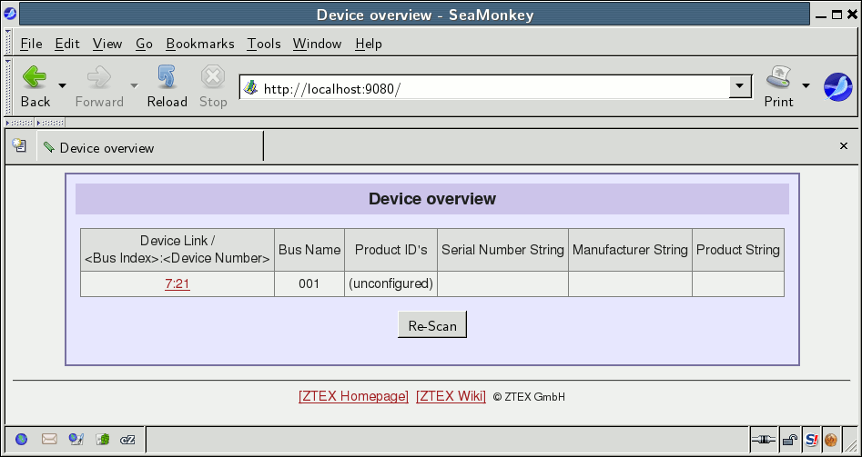
Step 1: Point you internet browser to localhost:9080 (provided that you started the DeviceServer with the standard settings) and click on the device link:

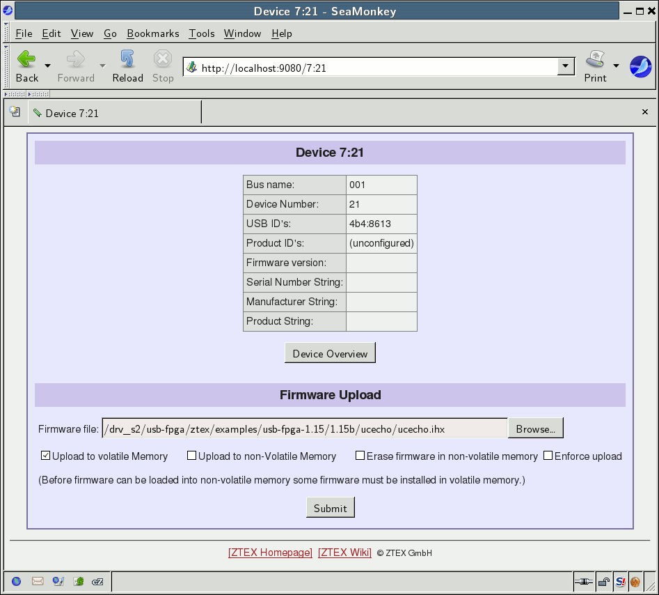
Step 2: Upload the firmware: Select the correct firmware, check the “Upload to volatile memory” and click the submit button.

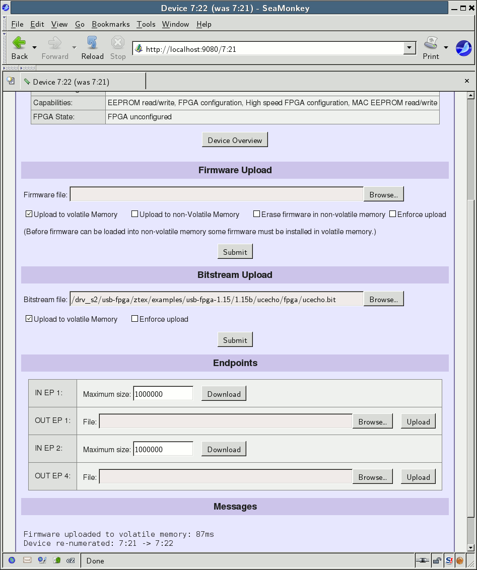
Step 3: Configure the FPGA: Select the Bitstream, check the “Upload to volatile memory” and click the submit button.
